A Networking Analogy

In the last blog we touched upon our PC getting connected to a server like Facebook, and showing the data in form of images and/or text. How are these data on the server getting downloaded to the PC and showing up in our local PC or laptop? 

Let us try an analogy to understand this a little better. Let’s say you ordered a bed from a furniture shop and the furniture shop told you that they will deliver it to your home. Assume your home is in a complex and there are many houses in that complex. 

The furniture shop dismantles the bed and makes into smaller packages. These smaller packages will be loaded onto trucks and the truck will deliver this to your home by checking your address. Let us assume for this bed it required multiple trucks to be loaded. Below will be how it will look like :-

The trucks(rather the truck drivers) are given the address of your house and at each signal in the junctions there is a direction board which tells the truck which direction to take for them to reach your house. Trucks follow the correct direction as told in the direction board and they reach your house correctly. Once trucks reach your home 

So at high level these are the steps done for the bed deliver from the furniture shop:-

  1. User or buyer in this case make a request to get the bed for his house
  2. The furniture store receives the request.
  3. Bed is dismantle and made into smaller pieces that can be loaded on to trucks to carry
  4. Sent the trucks to house by providing house address
  5. On the way the trucks will check for the directions by seeing the direction board and cross check with your home address to find the right route.
  6. Follow the sign in each intersection and finally reach house
  7. Once the trucks reaches your home it unloads and assembles your bed
  8. You get a complete bed in your home after proper assembly

What this has to do with networking. Let us keep it simple as of now. There is information or data(image/text) on the server. When your laptop browser(like Chrome/Firefox) connects to the server to get these information, the information are carried to your browser through the internet. How these information/datas are carried to your browser from the server is in a similar method how the trucks are loaded and sent to your house. 

Instead of house in the world of network it will be your laptop/computer

Instead of furniture shop it will be the server from where you requested information

Instead of bed you will be requesting for data in form of image, text, video etc..

Instead of trucks it is going to be packets and these multiple packets contain the information that you have requested for

Instead of roads in the networking world it will be connections using wired/cable or wireless connectivity

Instead of sign boards and signal junction it will be routers in the networking world. 

Well there are many other components that plays a role, but for now lets consider the most important element for the things to get working. 

At very high level these are the steps:-

  1. User make a request to get the data to his computer
  2. The server receives the request. Server can be Facbook, Google etc
  3. The data into small chunks called packet to be carried over the internet
  4. Send these small chunks of data from the server to your laptop browser.
  5. On the way through the internet check at each router for your laptop’s location. 
  6. Follow the information at each of the router one by one
  7. Once packets reaches your laptop, it assembles back those chunks in correct order
  8. You get the complete data from your server on your laptop after the assembly

In this scenario the furniture shop is your server and your house is the PC or laptop. The road that connects your house and furniture shop is the network. The bed along with the mattress will be delivered to your house possibly in a truck or multiple trucks based on the size of the truck and number of items the furniture shop wants to deliver to home.  Remember there will be a lot of signals and junctions where these trucks need to take the correct turns (please forget about Google maps for now) to reach your house and if the correct turns are not taken the furniture does not come to your house. 

When the truck starts from the furniture shop what it first checks is the town that your house belongs to and as the truck navigates through the road these trucks look for the town name board and take diversions accordingly. Once it reaches the town the truck driver looks for the apartment complex name, then your house number/name and finally it gets delivered to the house. Remember the bed is dismantled and all the pieces need to be fixed in the right order for you to get the bed in the way you saw it in the furniture shop.

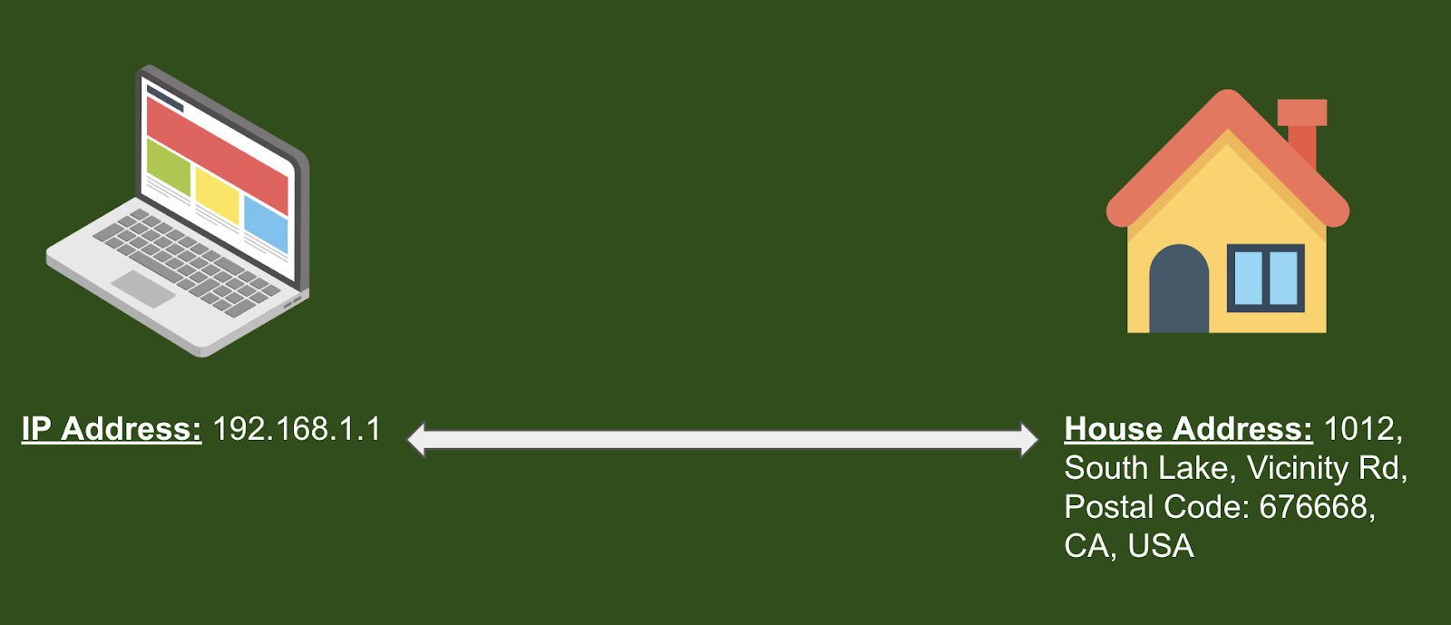
By and large this is how the PC communicates with the server and gets the data in terms of image/text to your laptop. Here the furniture shop is the server, your house is the laptop, the road is the network, directions are the route, town is the major subnet, your house number is the IP address, the room in which the bed is kept is the port number, the trucks are the IP packets.  Don’t get overwhelmed with all these. We will take one by one these items and explain in detail in the coming sessions. For now let us just understand that there is a similar mechanism happening in the network to deliver the content(bed in this analogy) to your laptop.

Subnetting Exercise

In one of the last blog we looked into an analogy of how a device in a network is by comparing the device to house in a housing community. We saw that some details on the address of a house are going to tell you which community house belongs to; example 1122, ABC Community, North Street, Castro Valley,CA-94087; tells us that house 1122 is part of ABC Community. Likewise IP address in combination to subnet mask is going to tell you which network the IP belongs to.
In this blog we will go through some exercise on how to identify the network when we get the IP address and Subnet Mask. We will also find out the range of IP address in the network, broadcast address and so on.

Let us start with a random IP address and mask 172.16.19.23/24

1. Find the network side and host side

For the IP Address 172.16.19.23/24 there are two parts, one is the network part and another is the host part. To find the network and host side of the IP address we should have a closer look at the mask in this case /24. In the blog subnet-mask-what-is-it-and-what-is-it-used-for we already talked about 3 different formats of subnet mask and how to convert between each of the network mask. /24 means there is 24 bits that is representing network of the IP address 172.16.19.23.

So in this simple step #1 we identified “172.16.19.” is the network side and “.13” is the host side.

2. Find the network ID by making all of the host bits to zero

To find the network ID after step #1 is very simple. Just make all the host bits to zero and now you get the network ID. In our example the network ID is going to be : -172.16.19.0/24 by making the last octet bits to zero. The network part is never going to change and in this example it is going to remain the same “172.16.19” and the host part will be different for different devices. In our example “.13” represents one of the device in the network “172.16.19.0/24”

3.Find the broadcast ID for the network 

If network ID is derived by making all the host bit to zero, the broadcast ID is got by making all bits in the host bits to 1. So in our example the broadcast ID is 172.16.19.255 (when all 8 bits for host is 1 then it is going to be 255).

Broadcast ID is a special IP in the network which is used to reach all the devices in the network.

4. Find the IP range that can be used in the network

To find the IP address range once you finish step #3, is just to find all the numbers possible for the host side which is between the network ID and broadcast ID. So it will be starting from 172.16.19.1 to 172.16.19.254

Subnet Mask & Network Design

Have you ever noticed a housing community? If you notice there will be a set of plots grouped together to build a community and that community will be provided a name. In that community each house will be identified by a house number. There will be multiple plots available and those houses get built as and when there is a requirement.  Also similar types of houses will be grouped together, like all premium houses will be grouped and placed in one community and all the apartments or townhouse/row-house in another group.

There is a similar concept in the networking world. Similar devices will be grouped together. For example devices like servers hosting the same kind of applications will be grouped together, printers will be grouped together so on and so forth. 

Like the housing community has a name to identify the group of houses for computer networks the group of devices is identified by a network address (also called as Network ID). Within the network there will be individual devices; like the houses in the community. And each device in the network will be identified using something called an IP Address. In our earlier post of A Network Analogy when the furniture was delivered the truck checks for the community address and once it reaches the community it checks the house number to deliver it to the right house. Similar things happens with internetwork. The IP packet (which is similar to truck in our analogy) which carries the data (furniture in our analogy) first make sure it reaches the network. Once it reaches the network it identifies right host (house in our analogy) in the network and delivers the data.
This means we need to clearly design the network so that the packets can reach the right network on the internet. The functionality that helps the network deisgner to efficiently group these set of device is subnet. To create a subnet you need 2 components

  1. Network
  2. Subnet Mask

The combination of network and subnet mask helps network designers to group the devices together.
What are the benefits of grouping these devices together with the help of subnet mask:-

Benefits of Subnet and Subnet Mask

  • Identify the host and network of an IP Address

Once you see an IP address along with the mask you will be able to identify which network that IP belongs to. Like having an housing community name attached to house is going to help us understand that specific house is part of the community (eg: No. 101, Crescent Village Community, Sunnyvale City, CA, USA, 90301. We first check the community name Crescent Village Community and then we find the 101 is a house in that community); these IP Address with subnet mask is going to help internet to identify IP is part of which network.(eg 200.1.1.1/24 is the par of 200.1.1.0/24 network and 200.1.1.1 is an device that is inside that network)

  • Ease of Troubleshooting

This about it, when city authority or government authority hear about the complaints from different houses that are not connected it will be very difficult for them to fix it for individual house. For example the drainage outlet is broken for few house. But when the houses are grouped in community then they need to check the connection given to the community first. This helps in easy identification issue and isolate them.
Similarly for the network administrator to find out and troubleshoot the problem reported by device is it important for group these devices into subnetworks so that the administrator can troubleshoot the network first and then go to individual devices in the network.

  • Ease of Operations

When a house needs an electricity connection is it easy for city/govermment to provide it based on individual house or it is easy to approve it to entire community. Offcourse for the entire community on the approval standpoint. 
When network administrator want to implement rules and restrictions in the network it does make a lot of sense to have subnet so that it is easier for them to operate. Example would be allow access to printers for employees; Allow employee network to access printer networks.

  • Segmentation of Network

The most important part is, subnetting helps the administrator to segment the network. Segmentation is fundamental components of new technology like Zero Touch Network Access. Segmentation happens at different layers and network is one of the layer. The subnet along with the mask is going to sub divide your network into smaller pieces which intern helps the administrator to make specific and strict rules.

Subnet Mask What is it and what is it used for?

Let us say that a housing project company that builds houses and apartments got permission from government to build 350 houses. The housing project company decided to build 50 premium stand alone house, 100 Row House or TownHouses and 200 Apartments. When the builder divide the entire land area he got to build the houses he dont need to allocate the 350 plot/site each for premium and Row/Townhouse and Apartments right? If he does that then it will be waste of plots as he is planning only 50 premium and 300 will be extra wasted plots for premium. Similarly for the Row/TownHouse and apartments he needs to check how many plot required for each and accordingly assign the plots.

There is a similar thing in the network designing and planning. Instead of apartments and standalone houses in our networking world it is going to be network and hosts. Usually the devices will be grouped based on the department and the kind of task that the devices does for ease of management and operations for the administrator. Example all the printers in one network, fax machine in another network, HR applications in another network and so on. And in each of these network the number of device will differ, like the houses in plot. 

The mechanism that allows this grouping of devices by making a set of of host and networks is called Mask, which we can loosely relate to the plot/site no. for the houses. The network mask helps us understand quite a lot of information. When there is a mask attached to the IP address it tells us which network that IP address belongs to. Mask also tells us how many number of hosts are possible in that network. We can also understand the IP address that we can use to broadcast the message to all the host in the same network. Mask also helps the network administrator to optimally use the IP Network that was assigned to him.

Let us understand more about subnet masks and how they are represented. Mask has 4 octets similar to the IP address.  Subnet Mask can be represented in three formats

  1. Binary Format
  2. Dotted Decimal Format
  3. Prefix Format

It is important to understand all the three formats and to convert between each of the formats. Let us understand each one in detai

  1. Binary Format

This is the format that will be used by routers and computers. In binary there are only 2 bits that you can use 1 and 0. As mentioned earlier the mask is used to represent the network side and the host side. In binary format the mask is represented with continuous 1s and then follows the continuous zeros. The 1s bit represents the network and 0s represents the host side. Let us take an example to understand this better

As the examples above the bits 1 will be continuous and then 0s will follow. The 1s and 0s are never interleaved. For example, a binary format of “111 0011. 0000 0000. 0000 0000. 0000 0000” for the subnet mask is invalid. So is “1111 1111. 0110 0000. 0000 0000. 0000 0000”. The rule for mask is simple it should be continuous 1s followed by continuous 0s.

2. Dotted Decimal Format

As part of the previous exercise we just saw the dotted decimal format. Convert each binary octet to decimal and you get the dotted decimal format.

Please note the each octet carries this value, which means we need to convert each octet like this. The rule of binary should be still met which means all continuous 1s followed by continuous 0s. Some of the possible and valid subnet mask are listed below

255.0.0.0, 255.255.0.0, 255.192.0.0, 192.0.0.0

But there below set of mask are not valid

255.192.255.0, 192.255.0.248, because when you convert values to binary you can see that there is no continuous 1s

3. Prefix Format

The last method of representing the IP address mask is prefix format represented with a “/” and a number after “/” Examples for prefix format is /8, /16, /20

The number coming after “/” is total number of continuous 1s in the binary format of subnet mask. Example

1111 1111.0000 0000. 0000 0000. 0000 0000 has total number of eight 1s in the binary subnet mask and hence the prefix format is going to be /8. 

Another example is 1111 1111.1111 0000. 000 0000. 0000 0000 has total of twelve 1s and hence the mask is going to be /12 and so on.

So the prefix can take value starting from /1 to all the way /32. Please note if we have all 0 then the prefix is going to be /0. We will cover more about that when we talk about default route/static route.

To convert from Binary to Dotted Decimal format is something we already so, summarized below:-

  • Convert each of the octet from binary to decimal
  • Write the decimal value with “.” between each octet

To convert from Dotted Decimal to binary convert each of the octet to binary with “.” between each octet.

To convert from Binary to prefix is pretty simple, just count the number of 1’s and the put / and the number after that /. 1111 1111.1111 1111.0000 0000. 0000 0000 has total of 16 hence /16 is the prefix format

Vice versa to convert from prefix format to binary, put as many 1s as the prefix says and rest all zeros. Example if there is a prefix /16 then put all the first 16 bits to 1 as below

1111 1111. 1111 1111.0000 0000.0000 0000

Finally if you want to convert the prefix to dotted decimal, the easiest way is to convert to binary first as it is easy to convert to binary and from binary to can convert to either easily. Another way to convert from prefix to dotted decimal is to device the prefix with 8. The quotient tells how many octets has 255 and if there is any reminder remember the table below

For example if you get a prefix /18 and you want to convert that to dotted decimal, then divide /19 by 8.

19/8 = 2 as quotient and 3 as the reminder. Since we got 2 as quotient the first 2 octet is going to be 255. For the third octet refer the table and if possible byheart the table; and the equivalent is 224. Hence the dotted decimal format is going to be 255.255.224.0

The same table can be used to convert the dotted decimal to prefix. First 2 octets are 255 hence 8+8 and for the third octet refer the table and you get the answer 3; hence 8+8+3 = 19. /19 is the prefix.

As we told at the starting the mask is going to tell the network to which IP address belongs to. So now if we combined the IP address and mask it will look like below

192.168.1.1/24 in prefix format

192.168.1.1 255.255.255.0 in dotted decimal format

192.168.1.1 1111 1111.1111 1111.1111 1111.0000 0000 in binary format

All these formats tell that the first 3 octets are part of network because 1s represent network and the last octet is host as all zeros represents host. So the IP address 192.168.1.1/24 belongs to network 192.168.1.0 which we call as the network ID and .1 which is last octet value represent the host in that network. To identify the broadcast address for that network make all the 0s(in binary) of host side into 1(in binary). Then you will get the value as 192.168.1.255 which is the broadcast address for the network.

Now let us take a real life scenario for a network admin who is designing his network. Assume you are appointed as a network admin for a Small Office Home Office(SOHO) which has 10 employees, 2 printers and 3 servers where there is some application running.  We need to design this network and identify the subnet mask that we need to use for this network. So since we need very less amount of host, the maximum being 10, we should use the class C address as per the blog post on IP Addressing. So let us take 192.168.1.0/24(ie masl 255.255.255.0) Class C network for this exercise.

IP Address Class

If you remember the network analogy that we used earlier in the blog furniture was successfully delivered to the correct house because the trucks(which is the IP packets in networking world) knows where exactly to go. Also if you remember every junction/signal has a board that has information about the which direction to take for you to reach the house.

The house address in our example above can be equated to IP addresses in the networking world. Because it is the IP address that uniquely identifies a laptop/PC/Server/Phone or anything that gets connected to network. And hence it is very important that the IP address needs to be unique because duplicate IP address will create confusion about whom exactly to communicate, similar to if there are same address for more than one house.

So if an IP address is a unique identifier like a house address, what is an IP network? An IP network is a group of addresses that can be grouped together; physically or logically(we will get into what logically means). You can think of an IP network as  a group of houses in the same community. The community will have the same name and individual houses will have a house number attached to it.

When house address across the world follow some formats like to have Country, State, Postal Code the rule in the networking world is a little different. IP address is 32bit dotted decimal number as shown below with 4 octets and each octet having 8 bits.  

If all the bit in the all the octet have the value of 0 then the IP address will look like : –

0.0.0.0 and if all the bits are having value 1 then it will be 255.255.255.255; when you convert the binary to decimal. 

When you have 0 for all the bits IP address in binary will look as below:-

When you have 1 for all the bits IP address in binary will look as below:-

This means IPv4 address can have take a range of IP Addresses from 0.0.0.0 to 255.255.255.255

These ranges of IP address are divided into 5 classes namely Class A, Class B, Class C, Class D and Class E.

Class D is used for multicast which means once a packet is sent to this IP address multiple devices(who are registered) are going to receive it if the device is registered or configured for the service. Class E is reserved for experimental purposes.

Let us concentrate our discussion with Class A, B and C as they are unicast IP addresses. Unicast means the packet is targeted to a single server or host. Let us understand how many different networks and host we will be available in each of these Classes.

For routers to identify which class that IP address belongs to there are few bits in each class that is reserved. Below are the reservations for each class:

If you convert the decimal value of the first octet of Class A address into binary the first bit will always be 0, and for Class B first and second bits will be always 10 and finally for class C the first 3 bits will be 110. This is a way to identify the IP address belongs to which class. 

For class A network the first octet ie first 8bits are reserved for network and rest of the 3 octets are reserved for host. Out of first 8bits the first bit is always 0 and hence the total number of network that can be formed in class A is  using 7 bits. Hence maximum number of first octet numbers that can be generated are 2^7. But 0 and 127 is reserved and that brings the maximum number of networks to 2^7 – 2 = 126. Which means the maximum number class A  network  available is 126 . Now if you check the number of hosts that can be created using a class A network is 2^24 – 2 = 16,777,214; 2 IP address need to be minused because 1 is broadcast and another is network ID(We will talk more about the network ID later). 

For Class B there are total of 16 bits(first 2 octets) for forming the network. But  since first 2 bits are always “10” the available networks that can be formed is using a combination of 14 bits, that means 2^14 = 16384 networks available and for each network there are 2^16 – 2 = 65,534 hosts available. 

For Class C there are 3 octets that are used for forming the network, but since first 3 bits are always set to 110 we have 21 bits remaining (24 – 3 = 21). Hence we have 2^21 =2,097,152 possible networks and 2^8 – 2  = 254 possible hosts per network.

Also notice for each of the Class there is a default netmask which tells how many bits are for network and how many bits are for hosts. For Class A default mask is 255.0.0.0 When we convert the dotted decimal mask 255.0.0.0 to binary it will be 1111 1111.0000 0000.0000 0000.0000 0000. All the 1 bits indicate that it is the network bits and all the 0 bits indicate those are the host bits. Similarly for each of class as show below:

Which class of the address to be chosen for your organization depends on the how large the organization is and how many hosts, and network will be needed for your organization. For example if you have fewer hosts needed then it is very clear that you can use Class C versus if you have a lot of hosts then you will use the class A network.

So to summarize; the unicast(address assigned/targeted to single host/server) can be broadly categorized into  3 Classes A, B and C. The IP address in any of the class has 2 parts

  1. Network 
  2. Host

The subnet mask of the IP address helps us to understand which is the network and which one is the host.

Network ID and Broadcast ID for Classful Network

Let us understand the network ID(also called as network address or simply network) and Broadcast ID (also called as broadcast network address or network broadcast). As we have seen earlier depending on the class IP address belongs to we assign some bits for the network and some bits for hosts.  For example if it is class A then the first octet is reserved for the network and the rest of 3 octets for host. 

Lets take an example 10.1.1.1 IP address. Based in the first octet it is clear that the IP address below to Class A and default mask is 255.0.0.0. Hence the network part is 10 and host part .1.1.1

Network ID is the IP that we get when we make all the host bit to zero. In our example the host part .1.1.1; ie the last 3 octets when we made all of the binary bits  to 0 the IP address will look like : –

10.0.0.0 which is the network ID for the IP address 10.1.1.1

Broadcast ID is the IP address we get when we make all the host bit to 1. So in our example the host part .1.1.1; ie the last 3 octet if we made all the bits(in binary) to 1 then the IP will look like

10.255.255.255 which is the broadcast ID.

The network ID and broadcast ID is reserved and can not be assigned as an IP address to any host in that network. So given an IP address for us to find the Network ID and Broadcast ID is a pretty simple 4 steps process.

  1. Identify which Class the IP address belongs to
  2. Split the network part and host part
  3. To get the Network ID make all the bits in the host part to 0
  4. To get the Broadcast ID make all the bits in the host part to 1

AWS Region & Availability Zone

When we talk about Cloud computing since the word cloud is there we tend to think that it is somewhere up not reachable to us. I remember in my early network admin days when asked someone where does the networking cable go, he answered “it goes inside the wall and the wall takes care of the rest”. Similar is the case with cloud today, many does not have a clear picture of where these resources stay. 

In this writeup we will see when a user creates an instance or stores some data in AWS how and where AWS creates this instance and stores this data.  

What does AWS region mean and what does it mean by saying Availability zone?

When we say my applications running  in a  AWS region and Availability zone where exactly are these residing?

Since the blog is about a bottom up approach let us start with the fundamentals. We have talked about the fundamentals of virtualization in this blog. Even though the word cloud makes us look up, it is really the brick and mortar, meaning the physical building and server that is underlying which enables all these technologies. In reality if we zoom in and see what is the building block we will be able to see that all the workload is stored in the physical building and servers in that building. One of the core technologies that is being used to enable all these cloud capabilities is virtualization which is enabled on each of these servers in the building. 

Lets dig deeper and understand how these are built.

When you launch a workload in AWS you will be running the instance in a Region and within a region you will be running it in an Availability Zone.

Let us understand what AWS Regions means and why as a user/customer we should care about. When we talk about AWS Region we need to talk about Availability Zone as well and how they are related.

As mentioned earlier everything starts in the building where there are servers. Every server and OS is enabled with virtualization. If we zoom in and see what is AWS Region and Availability zone it starts with a building and having multiple servers in it. Let us say you asked a person who has accessibility and working in Amazon AWS to show you where exactly your instance is residing. He is going to take you to a physical building like this.

When you get inside this building you will be able to see a lot of servers in the building as below.

Each of these servers will be connected to each other over high speed connectivity. Multiple of these server racks and/or the complete building having these servers are called datacenters(DC).

Amazon AWS will be having multiple of these Data Centers and all these data centers are also interconnected with high speed connectivity.

There will be multiples of such data centers. A group of these data centers ie 2 or more of these data center is what AWS refers to as Availability Zone.

A group of multiple Availability Zones is a AWS Region

As of this writing AWS has 31 launched regions and 99 Availability Zones. This numbers are going to grow.

This begs the answer to the question why did AWS design the data center this way to have the Availability Zone and AWS Regions. If you guys have not guessed it, the answer is pretty simple. One of the key benefits of cloud is availability to run the business all the time up and running. When you run you application and data in AWS you have the option to use multiple availability zones so that even when one of the data centers goes down your application is not completely affected. So when one datacenter goes down you have the data in another data center as you have architected the application to run in multiple Availability Zones. Remember it is your responsibility to have your architecture to use multiple availability zones for redundancy.

As we have seen, the Availability zone is in the AWS region. Customers select the region based on multiple reasons. Four most important driving factors for the customer to select a region is 

  • Compliance:- 

Depending upon the business your company is in, there will be need of different compliance to met. For example if you are in financial sector and you are having the details of customers like Credit Card information there are regulation on where the data should reside. There will be compliance like the user data should not go out of the geography of your country. So when you deploy you application and store the customer data you should make sure you have selected the region that is compliant to business regulations.

  • Service Availability

Another important item to consider is the availability of AWS service. Not all region in AWS has all the services in AWS. Especially for the new services the AWS roll out you should make sure that the region you select has that service available there.

  • Geolocation:

Another important thing for you business is where does your customer residing. Your application needs to be closer to the location of your customer. This will ensure the best experience for your customer with minimum latency.

  • Cost:

Last but not least is the cost. When you try the service in different region the cost may vary. And it is important for your business to select the region which is most cost effective. Your decision should be a balance of all these.

AWS EC2 Instance- Which One to use

When you select an instance in AWS for running a workload and/or your application there are few key things that you need to consider before selecting the type of instance. Mainly that comes under one of the below:-

  • Is your application going to need a lot of compute power, like a high performance processor?
    • These would be applications like gaming servers
  • Will  your workload/application computing need be met with software running on CPUs and would need hardware accelaration?
    • This would application like data pattern matching or image processing
  • Does your workload/application require a huge amount of data to be loaded into memory?
    • Eg: would be application reading from in-memory database rather than reading 
  • Does your application require a lot of read/write I/O operations to be performed?
    • Eg: your application read the data from storage DB like elastic search DB.

Based on the amount of compute, memory, storage needed for your application you have the option to select different family of instances. Within each family of the instance you have multiple instance type for you to select.

There are six major family of instances available in AWS:-

  1. General Purpose:

If your application is in need of almost equal amount of compute, memory, storage then you should use General Purpose instance family

  1. Compute Optimized

If your applications are like a gaming server or streaming server then you should prefer Compute Optimized.

  1. Memory optimized

If your applications are more towards loading a lot of information in RAM for processing ie the applications like big data analytics apps such as Hadoop, then you should prefer a memory optimized instances family.

  1. Accelerated Computing

Suppose your application’s main task is video rendering or doing remote workstation where there is a need to have high fidelity graphics in real time, then make sure your instances are from Accelerated Computing.

  1. Storage Optimized

If your application needs a constant and high speed reading and writing into databases, make sure your instance family is from Storage Optimized family.

  1. High Performance Computing Optimized

Purpose built to offer best price performance, for application that does large complex simulation and deep learning workload.

Why and Why Not Cloud

Lets try to understand the benefits of cloud computing through its fundamentals. 

To understand cloud computing it will be a wise thing to understand what forced its invention.  Let us see how things were working before cloud so that you understand the real need of cloud and key benefits that it brings, in plain simple language and free of jargons.

Fig.1 shows a user accessing an application over the internet.  Application could be any application,  but for this example let us say it is Amazon.com, which is world’s largest online retailer. So in this case it look very simple a user is accessing Amazon.com, browsing and buying some products; remember this is an era when cloud computing was not invented.

What we are interested in is  how the Application is hosted, ie the details of the server, the resources in the server in terms of memory, storage, cpu etc and also how the application is using these resources. Again, remember we are talking about the era before cloud computing was born.

Figure:2

As fig. 2 shows for running this application we need a hardware server with some amount of cpu, memory and storage which will be utilized by an Operating System like Windows or Linux.  But how do somebody come up with the right amount of those resources? Yes off course the developer know the resources that is required for the application to run for a fixed number of requests that need to be processed by the application.  

Figure: 3

But since this is Amazon the number of requests vary drastically across different seasons, sometimes differ drastically even within different hours of the same day. As in fig.3 what happens when there are 1000s or even millions of requests. The only way to accommodate that in the pre cloud computing era is by forecasting the highest number of requests that are going to come in and buy the server or upgrade the server with such resources. For example do capacity planning and say for 1million requests to be handled we need a high end server with a huge amount of CPU,  MEMORY and Storage.

Maybe you have guessed the problem already with this approach. Yes, apart from the time there is a huge amount of traffic these resources are underutilized. Businesses have to pay for these servers and it gets used to its fullest capacity once in those holiday seasons when there is maximum traffic/requests. There are further more problems. Let us say the architect found a new or better database for the application. He has to refactor the complete application and repackage application to install it again.  When he does the reinstallation he has to make sure the server on which currently the application is running supports the new database. If it does not support the new database then the  business needs to buy a new server or atleast there may be a need for some hardware component upgrade which costs more money now.

So let us list down the list of problem with this approach:-

  • Scaling Issue: As we saw, we need a high-end system with loads of memory/CPU/storage to address high traffic and companies or the network/application architects do a capacity planning. But what if for some reason traffic is higher than the anticipated traffic at the time of capacity planning. Then the company has to procure new hardwares again to address these needs.  Which in technical terms we say not easily scalable.
  • Flexibility Issue:  Depending on the need we are not able to adjust the resource and expense. Which means if traffic is low I should be able to use less resource and if traffic is more I should be able to use more resources, which is not possible with this model because to increase or decrease the resource we need to make hardware changes. In technical term we call this as not flexible.
  • Security: Remember these servers are physically accessed by humans in the datacenter. When there is change that needs to be done on the hardware those are accessed physically. Also in this model there is no specific granular restriction on from where the server and its content are accessed.All the data in the server have almost same access restrictions. Let us call this as Security Concerns.
  • Visibility As we already saw as part of security almost all data residing on the server has same access restriction. Who access it, which part of the entire data was accessed, at what time these details are not provided with this model. Let us call this as visibility.

When there are many more benefits for cloud let us stick to these 5 items for the time being.

When companies were running their businesses with these kind of issues, there already existed a technology which did not have its real usage for a very long time. That technology is Virtualization. What virtualization does is, it allows multiple OS to run on the same hardware by providing virtual instances of our limited resources: CPU, Memory and Storage. Applications can be installed on these OS. 

That was a great shift and saved a few of the issues to an extent. The architecture changed from previous one to a new one as in below figure 4. I can have multiple application may be same application that can do load balance the multiple request. But remember still there is a limit on the total CPU,RAM and Storage, because you can virtualize to the max of how much hardware RAM/CPU/Storage you have. That means the problem  above we listed is still not solved.

Figure: 4

Then how about if I can have a pool these resources, and then run some automation to help create the virtual resources and deploy application as and when needed? Is it possible? If it is possible then companies can rent out that service to store the data. 

It is possible and that gave birth to today’s data center “Cloud” based data center.

It will look like in figure 5. Pools of resources shared and cab create the application using the required resources.  

User should be able to create virtual CPU, virtual Storage, virtual Memory through few clicks or programmatically. In case they want to increase any of the these virtual resources they can do it in few clicks or by running a small program. On top of those virtual resources operating system and application can be installed.

Let us look back to those 5 issues and see if this new approach is solving it or not.

  • Cost: with few clicks or by running a program we can increase or reduce the resources as needed. The new approach or model can be now be adjusted to bill the customer based on the resources that have been consumed.  Taking the earlier example of users trying to buy items from Amazon.com, we can program to check the amount of traffic coming in and say need more resources as we see the more traffic. Companies need not buy large configuration server just because in some seasons traffic is going to go higher. Pay as you use.
  • Scaling Issue: whenever more resources are needed you can add instantaneously as we saw earlier. We can even have a program to do it and no need of human to look at it. Auto scaling .
  • Flexibility Issue: Resources are added or removed as needed based on the environment. Which means now we have flexibility and elasticity 
  • Security: The component needed for application to work like DB, front end infrastructure etc can be hosted on different hosts and provided very specific access right.  Also for expanding the resources it is just few clicks and no human physical intervention is needed. This provides granular security.
  • Visibility: with granular access control comes deeper visibility. Who accessed and what time each of the application was accessed is looged. Sometime it may not be user accessing the application,  it may be an application using another application. All those are monitored and logged which provide deeper visibility. 

That is the world of cloud.